
 English


A rotating video link can fail for reasons outside the slip ring itself. Loose connectors, damaged coaxial cable, poor strain relief, contamination and grounding changes can all affect the complete path. Maintenance should therefore cover the installed rotary interface rather than focus only on the internal contact assembly.
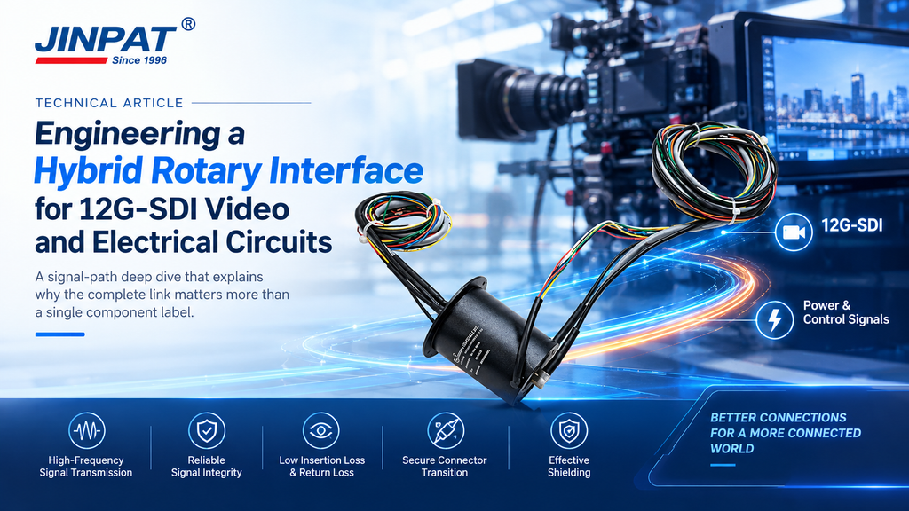
LPT000-0405-06S-HF01 combines an integrated high-frequency path for 12G-SDI transmission with other electrical functions and uses a radial stator-side cable exit. Its original application is a radar antenna. The following maintenance framework is suitable for planning, but the approved product manual must define the actual limits and procedures.
Record the installed model, serial reference, drawing revision, cable part numbers and connector arrangement. Photograph the cable route and strain-relief points. Note the rotation profile, operating schedule and environmental conditions. These records help technicians distinguish an original design detail from a later field change.
Commissioning should also establish a functional baseline for the video link. Use the system’s approved test method and save the result with the configuration. A later comparison is more useful than a general statement that the picture looked acceptable on the first day.
A radial cable exit needs enough clearance so the cable is not pressed against surrounding structure. Check bend radius, clamps and strain relief. Look for abrasion, twisting, loose hardware or a cable that has begun to carry the weight of another component.
Inspect connectors for looseness, contamination and mechanical damage. Do not clean or lubricate connectors with an unapproved material. If the system uses adapters, include them in the inspection because they form part of the high-frequency link.
A calendar interval alone does not describe wear. Review operating hours, speed, reversals, vibration, dust, humidity and load. A system that rotates occasionally may need a different plan from one that runs continuously. The manufacturer should approve the final interval and the actions permitted in the field.
Maintenance records should capture repeatable observations: connector torque where specified, visible cable condition, abnormal noise, temperature observations using an approved method, video-link test result and any replaced part. Trend changes rather than waiting for a complete loss of transmission.
If video becomes intermittent, document whether the symptom depends on angle, speed, temperature or cable movement. Check accessible external connections before disassembling the slip ring. Substitute test components only under a controlled procedure so the team can identify which change affected the result.
Do not diagnose a high-frequency problem from a static continuity check alone. A circuit can show continuity and still perform poorly at the required data rate. Use the approved source, receiver and cable arrangement for confirmation.
Remote installations benefit from a configuration-specific spare-parts list. Include the correct cables, connectors, mounting hardware and any service tools approved by the manufacturer. Keep drawings and procedures in the language used by the local team.
A disciplined baseline, regular cable inspection and controlled link testing can reduce unnecessary component replacement. They also provide useful evidence when the supplier needs to evaluate a returned product or propose a revised rotary interface.